![]()
![]() SPANISH VERSION
SPANISH VERSION
Model 201/207/209/221/227Short Haul Modems and Line Drivers Reference Manual 0315-0227 Rev. D
Printed 11.13.02
|
Table of Contents |
|
1.0 General
Description 6.0 Connector Pin
Assignments |
1.0 General DescriptionThe Model 201/207/209/221/227 performs full-duplex transmission of asynchronous data over four wires (two twisted pairs). The data transmission between each line driver utilizes differential signaling that is immune to electrical interference and therefore makes it ideal for use in light manufacturing and industrial office areas. All five models are compatible with each other up to speeds of 19.2 kbps, while the Model 207/227 operates up to 115 kbps. 1.1 DataSpy Feature (Model 221/227)Your new Telebyte product incorporates the Patent Pending DataSpy feature, an LCD display designed to assist with initial installation and check-out. Thereafter it can be used as a performance monitor. In the case of a system problem it provides information as to the status of the local link.
|
|
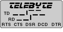
The display of the Telebyte logo on the LCD display indicates
that the unit is powered. For power stealing devices such as a modems, it
indicates that sufficient power is being applied to operate the device. The LCD
display uses less than 1 milliwatt of power. The LCD display also shows the status of the following control signals: CTS, RTS, DSR, DCD, and DTR. These signals are displayed as mnemonic symbols, composed of three letters each, on the bottom line of the display. The presence of the three-letter mnemonic indicates that the respective control signal is high (positive). |
|
|
|
2.0 Specifications2.1 InterfaceConnectors RS-232: Analog: Model 201: RJ-11 and four screw terminals. |
|
Note: The Model 201/207/209/221/227 can be ordered with an RJ-45 installed, in place
of the RJ-11, by adding "P2" to the end of the respective model number
(e.g., 227MP2). Model 201/209/221: 0 to 19.2 kbps. Model 207/227: 0 to 115.2 kbps. 2.3 TransmissionAsynchronous full duplex over four wires (two twisted pairs). 2.4 SwitchesEach modem is equipped with a DTE/DCE switch to allow reversal of the TD and RD signals on the RS-232 interface. 2.5 IndicatorsThe Model 221/227 is equipped with an LCD display for data, five control signals and power. | |||||||||||||||||||||
| |||||||||||||||||||||
|
|
1.3" W x 3" L x 0.75" H Model 221/227: 2" W x 4.15" L x .79" H 2.9 Environment 0 to 50o C, 5 to 95% relative humidity.
3.0 Installation3.1 Digital Interface3.1.1 The digital interface for the Model 201/221/227 is a DB-25 connector. The Model 201/221/227 may be ordered with either a male or female connector. The gender of the connector is indicated by the first letter in the suffix of the model number. For example, the Model 201M has a male connector and the Model 201F has a female connector. 3.1.2 The digital interface for the Model 207 is a DB-25 male connector. The Model 207 comes equipped with a mini gender changer if it is necessary to interface to a male DB-25. 3.1.3 The digital interface for the Model 209 is a DB-9
female connector. |
3.2 Analog InterfaceNote: The four-wire line between modems must be two twisted pairs. On each modem, the
wires marked T+ and T- must be members of the same twisted pair and those marked
R+ and R- must members of the other pair. The Model 201/209FT is supplied with four screw terminals marked T+, T-, R+ and R-. The Model 207/221/227 is supplied with five screw terminals marked T+, T-, R+, R- and GND. When connecting two line drivers together the T+ terminal of one unit goes to the R+ terminal of the other; the T- terminal goes to the R- terminal. 3.2.2 Phone Plug The Model 201/207/221/227/209FP is equipped with
a standard RJ-11 modular phone connector. Only four of
the six positions are used. If ordered with the RJ-45 option
(P2) only the four middle pins are used. The designation of
the wires is shown on the next page. |
|
|
4.0 Operation
4.1 Model 201/207/221/227This model is equipped with a DTE/DCE switch that allows for reversal of Pins 2 and 3 of the RS-232 connector. When the switch is in the DTE position, Pin 2 of the RS-232 connector is an output (transmit-to-host device) and Pin 3 is an input. When the switch is reversed to the DCE connection, Pin 2 becomes an input and Pin 3 an output. When interfacing to a terminal or PC the switch should be in the DCE position.
|
4.2 Model 209This model is equipped with a rotary DTE/DCE switch that allows for the reversal of Pins 2 and 3 of the RS-232 connector. When the switch is in the DTE position, Pin 3 of the RS-232 connector is an output (transmit-to-host device) and Pin 2 is an input. When the switch is reversed to the DCE connection, Pin 3 becomes an input and Pin 2 an output. When interfacing to a terminal or PC, the switch should be in the DCE position. A small screwdriver is supplied to facilitate the switching. 4.3 Model 221/227The LCD display verifies operation. |
|
|
5.0 TroubleshootingThe following is a list of problems that may occur during the installation and some suggested solutions. 1. The data being received is garbled.
2. No data is being received.
3. The Data is clear at first and then becomes garbled.
|
|
If the unit is believed to be defective, operation can be verified if one of the devices to which the modems are attached is capable of operating in a full-duplex mode (e.g., a terminal or a PC using a communications package such as Procomm). Connect the Model 201/207/209/221/227 to the terminal via the RS-232 connector and make the following loopback connections at the analog interface: T+ to R+ and T- to R- If the modem is functioning correctly, any data entered on the keyboard should appear on the screen. |
|
|
6.0 Connector Pin Assignments
| |||||||||||||||||||||||||||||||||||||||||||||
| |||||||||||||||||||||||||||||||||||||||||||||
|
* These signals can be reversed using the selector switch.
|
6.2 Model 209 | |||||||||||||||||||||||||||||||||||||||||||||
| |||||||||||||||||||||||||||||||||||||||||||||
|
* These signals can be reversed using the selector switch 7.0 Power7.1 Model 201/207/221/227This model can be powered in one of two ways:
|
7.2 Model 209This model can be powered in one of two ways:
8.0 HelpIf you require assistance, please visit our
Technical Support
Center. WarrantyTELEBYTE warrants the equipment to be free from defects in material and workmanship, under normal and proper use and in its unmodified condition, for 12 months, starting on the date it is delivered for use. TELEBYTE's sole obligation under this warranty shall be to furnish parts and labor for the repair or replacement of products found by TELEBYTE to be defective in material or workmanship during the warranty period. Warranty repairs will be performed at the point of manufacture. Equipment approved for return for warranty service shall be returned F.O.B. TELEBYTE factory and will be redelivered by TELEBYTE freight prepaid, except for non-continental U.S.A. locations. Non-continental deliveries will be sent COD freight plus import/export charges. The above warranty is in lieu of all other warranties, expressed or implied, statutory or otherwise, including any implied warranty of merchantability or fitness for a particular purpose. TELEBYTE shall not be liable for any damages sustained by reseller or any other party arising from or relating to any equipment failure, including, but not limited to consequential damages nor shall TELEBYTE have any liability for delays in replacement or repair of equipment. Out of warranty equipment may be returned to the Greenlawn, NY customer service facility prepaid as described above. Return shipping charges will be billed to the customer. The repaired unit will have a 90-day warranty. In those cases where "NO TROUBLE" is found, a reduced charge will be billed to cover handling, testing and packaging. Whether in or out of warranty, a Return Material Authorization (RMA) number is necessary and can be obtained by visiting our Technical Support Center. Reference the RMA number on the outside container.
|