Within the premises or local area environment the short haul modem is a
convenient device for configuring a reliable communications link. When
the distance between communicating data equipment gets beyond 100 feet
signals need 'to be boosted' or they will not be received and decoded
reliably. Using a pair of short haul modems in the link, one for
transmitting and one for receiving in each direction, boosts the signals
and gives the reliability.
However, a number of items always seem to come up when using a pair of
short haul modems to deal with this rather straightforward problem.
First, there is the matter of isolation. The need for isolation arises
when ground currents are present. In many instances the data equipment
communicating must be grounded at different points. Different grounds
imply different reference levels for voltages. Ground currents are
generated in an attempt to achieve equilibrium between different ground
points. From the perspective of communications such currents make
themselves known as an additional interference mode. Isolation provides
a barrier between different ground points. This barrier does not allow
ground currents to be generated. Isolation allows equipment being
grounded at different points to be connected together without the need
to worry about the interference due to ground currents.
Secondly, there is the question of flow control. It may be that one of
the communicating data devices is ready to transmit, but the other is
not yet ready to receive. It may still be carrying out a prior task.
Flow control procedures assure that communications only proceeds when
both devices are ready. Often these can be carried out by software, but
not always. In the absence of software flow control there is frequently
a demand for a hardware flow control feature - a hardware 'handshake'
between both ends of a link. This often is as simple as one end of the
link raising the DTR (Data Terminal Ready) flag, sending it to the other
end of the link which responds with the DCD (Data Carrier Detect) flag.
Finally, there is the 'headache' of getting the data communications link
up and running. Something always seems to happen, and the installer
always has to look at some signals going from one end of the link to
another. The installer has to look at the status of the link and maybe
even after the link is up the user has to check status from time to time
to assure himself/herself that everything is OK.
These issues must be dealt with in the context of the modem supporting
the data rate needed for communications over the distance required by
the communications.
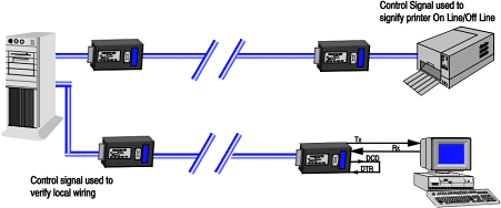
All of these issues can be conveniently handled by the Model 224 short
haul modem. Its employment in a typical application is provided by the
illustration above.
Here we have a host computer on the left. It has two ports. Through the
upper port it is communicating with a printer. Through the lower port it
is communicating with a PC. In both cases, full duplex, asynchronous
communications is required. The printer is getting text to print out and
is sending status messages back to the host computer. The PC is acting
as a terminal relative to the host computer, which may be serving other
PC-terminals as well. The PC is sending queries to the host computer and
receiving responses back. In the case of both the upper and lower links
bi-directional control signals are required. The printer needs them
because it may not be able to keep up with the text being sent from the
host computer. The PC-to-host computer link needs them because the host
computer may be too busy with other tasks to serve the PC at a
particular time. The distances and required data rates in both cases are
moderate - being at about 1 mile and 19.2 KBPS. Since equipment is
necessarily grounded at different points ground loops may be present
with the possible deleterious effect they have on performance.
Pairs of the Model 224 can be used to implement the data communications
link from the upper port to the printer and from the lower port to the
PC. The pairs of the Model 224 on each link can provide the necessary
full duplex, asynchronous data communications over the necessary
distance and necessary rate. The Model 224 is optically isolated.
Consequently, it can ameliorate the effects of ground loops. It can
support a bi-directional control signal. Thus, it can provide the flow
control required by both the upper and lower data communications link.
The Model 224 shown in the illustration fits the needs of this
application quite well. It is a full duplex, short haul modem where full
duplex is achieved by using two separate cable pairs. It transmits data
in an asynchronous mode. The Model 224 can transmit at data rates up to
19.2 KBPS for links of about 1 mile on 26 AWG cable. It can provide
reliable transmission for up to about 10 miles if a lower data rate of
1.2 KBPS is OK.
Finally, the Model 224 has a convenient LCD display for showing link
status. This effectively integrates a breakout box right into the modem.
It allows the network manager to view the status of the data lines and
the interface control pins. It is ideal for helping bring the link up
and for monitoring its proper operation.
The previous illustration showed just two ports on the host computer.
You may have a similar application, but data communication is being
carried out from many ports on a host computer. The illustration above
shows such a situation. In this case it may be more convenient to rack
mount the short haul modems on the host computer side. The Model 79 is a
rack mount version of the Model 224 and is ideally suited for these
circumstances.
|


